Home
>
Facing options for reinforced soil slopes
Technical note
10 Min read
>
10 Min read
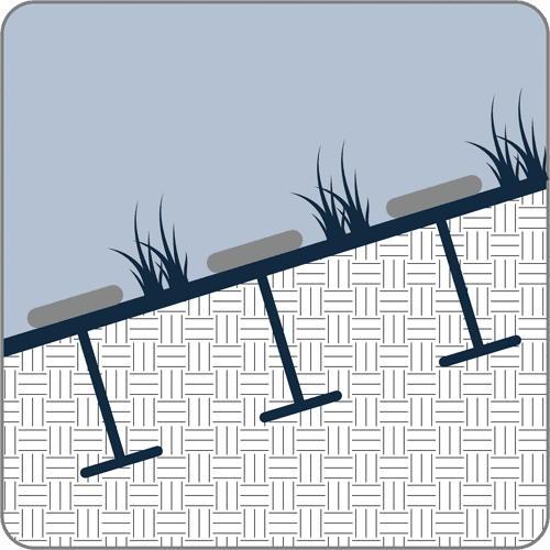
Reinforced soil slopes (RSS) are defined as structures with face inclinations of less than 70 degrees from the horizontal (FHWA, 2009a). A critical aspect of the design of reinforced slopes is the facing system. The erosion protection facilitates vegetation establishment and/or provides structural support for forming “over-steepened” slopes. The secondary reinforcement facilitates compaction and helps prevent surficial sloughing at the slope face. Figure 1 shows a general cross section and the various components of a reinforced slope system.
The stability of a slope can be threatened by erosion due to rainwater impact and surface water runoff, or more severe erosive forces associated with water currents and wave attack. Slope face erosion may create rills and gullies, and result in surface sloughing and possibly deep-seated failure surfaces (FHWA, 2009b). Therefore, erosion control and re-vegetation measures must be an integral part of all reinforced slope system designs and specifications. General facing systems include ‘soft’ or vegetated and ‘hard’ or armored systems, which may or may not include a geosynthetic face wrap. This Technical Note provides guidance on the selection of geosynthetic reinforced slope facing systems.
A face wrap is generally not required for slopes flatter than 1(H): 1(V), if the reinforcement (secondary and/or primary) is maintained at a close vertical spacing (FHWA, 2009b). In this case, the reinforcement can be extended to the face with subsequent placement of the erosion protection. Alternatively, the slope face may be over-built and subsequently cut back to the desired slope grade. However, care must be taken to prevent damaging the reinforcements at the slope face. Figure 2 and Figure 3 illustrate the two typical methods of forming the face of a reinforced slope without a face wrap.

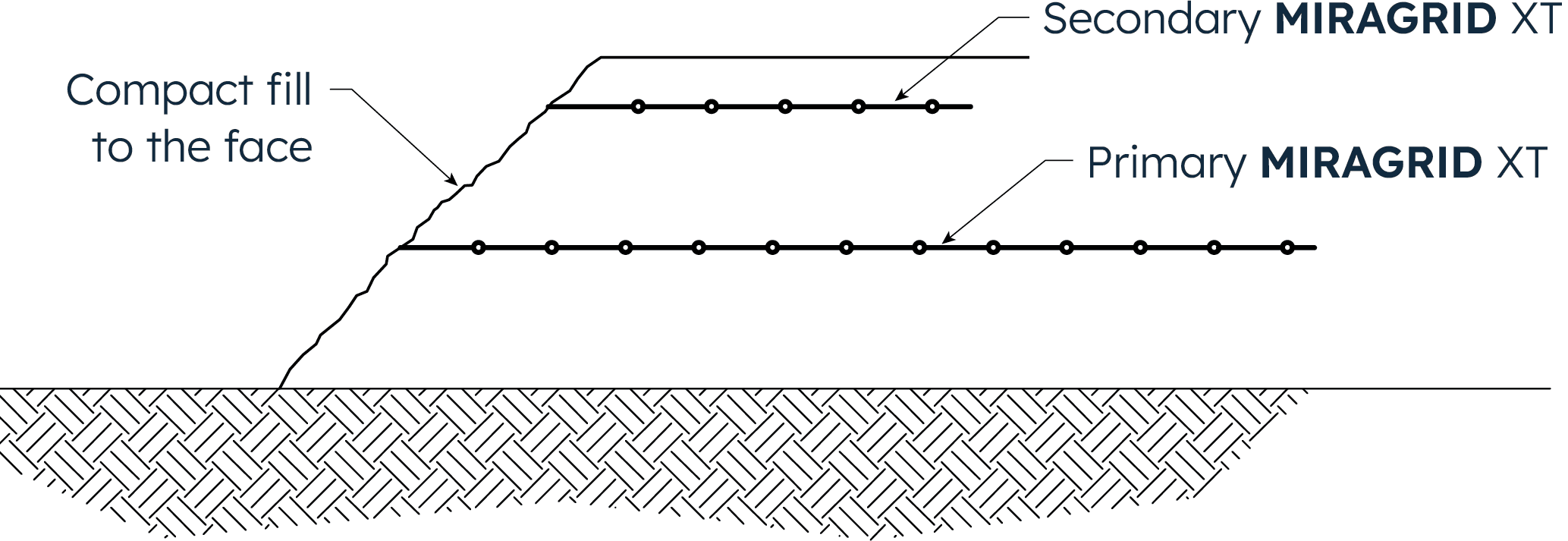
Figure 2: Compact reinforced fill to the finished face

Figure 3: Construct reinforced backfill beyond the finished face, compacting lifts and cut back to final grade at end of construction
Reinforced 1(H): 1(V) slopes constructed with most soil types and not subjected to severe erosive forces should be vegetated after construction to prevent or minimize erosion due to rainfall and runoff on the face. A synthetic erosion control mat may be used as a permanent facing but must be stabilized against ultraviolet (UV) light (FHWA, 2009b). Figure 4(a) shows a typical cross section with PROPEX® Pyramat® 75, a synthetic high performance turf reinforcement mat (HPTRM) with UV stabilization to provide a design life of up to 75 years and Figure 4(b) shows PROPEX Pyramat 75 being installed on the slope face.
The erosion control mat serves to (FHWA, 2009b):
protect the soil slope face from erosion until vegetation is established;
decrease the runoff velocity allowing for increased water absorption by the soil, which promotes the longevity of the vegetative cover; and reinforce the root system of the vegetative cover.
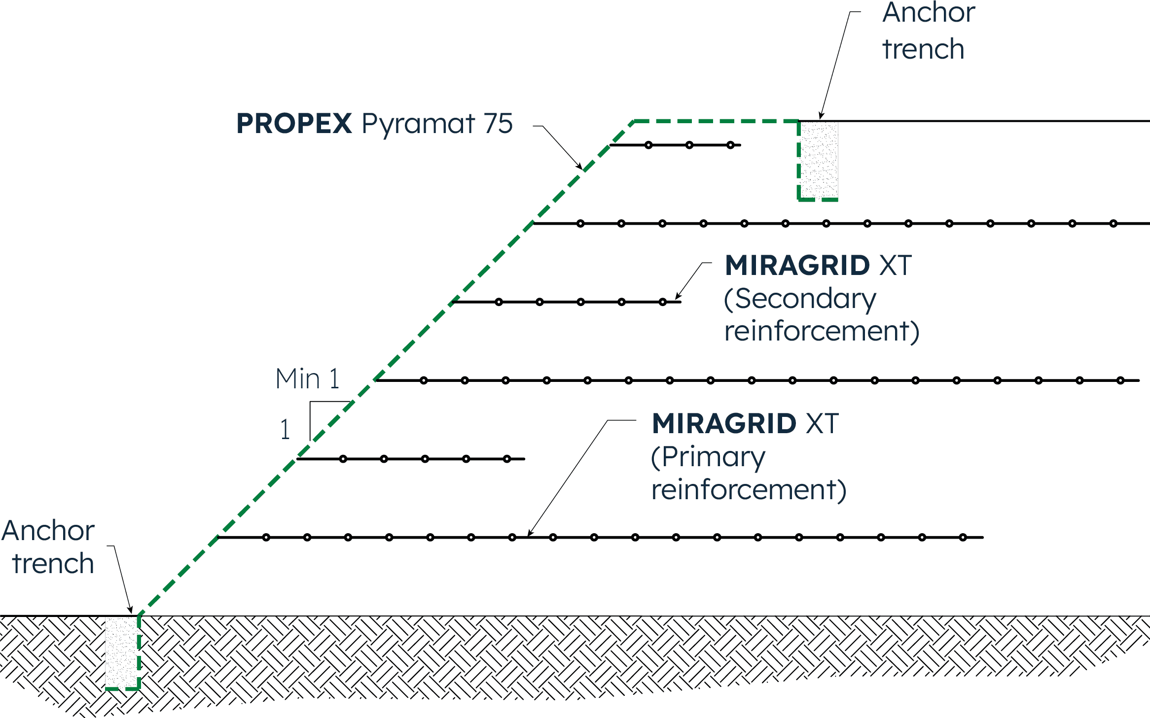
Figure 4(a): A typical reinforced soil slope with PROPEX Pyramat 75, a high-performance turf reinforcement mat (HPTRM) for UV stable erosion protection
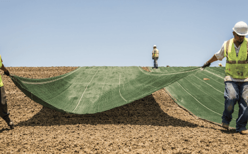
Figure 4(b): Project photo of PROPEX Pyramat 75 being placed on the slope face
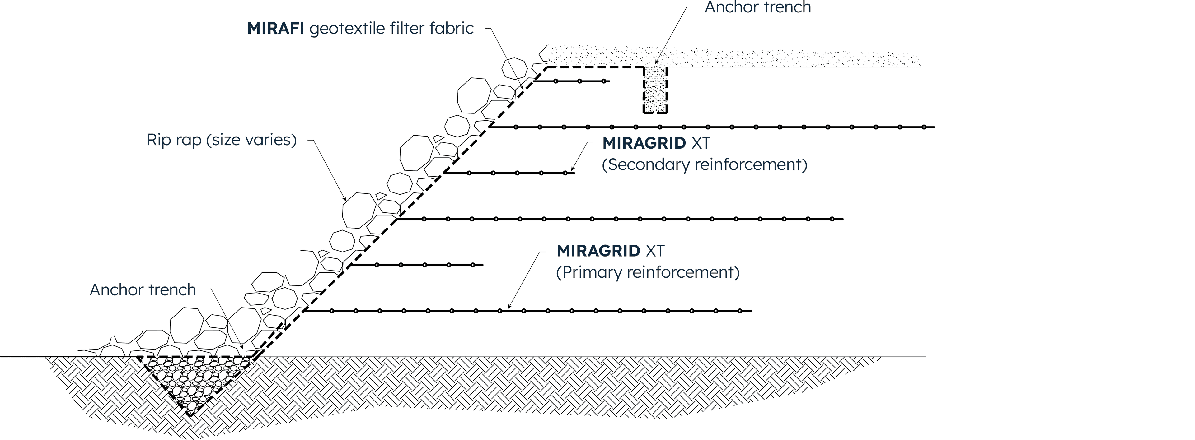
For reinforced slopes subjected to severe erosive forces associated with water currents and wave attack, the erosion protection system must be specifically designed to resist these forces. Typically, these severe cases will require a ‘hard’ armor erosion protection system such as riprap, gabions, articulating concrete blocks, or fabric-formed concrete. A geosynthetic face wrap is not generally incorporated; however, a geotextile filter should be placed along the slope face, underneath the erosion protection system. Figure 5 shows a typical cross section with rip rap (hard armor) erosion protection.
Another option for hydraulic loading or locations where erosive forces or scour are likely to occur is PROPEX Scourlok®. This system is designed for these applications. For more information on PROPEX Scourlok, please see the Solmax Technical Note on nature based erosion control solutions.
Reinforced slopes that are 1(H): 1(V) and steeper typically require facing support during construction (FHWA, 2009b).
A geosynthetic face wrap and/or a hard armor facing support system is often used in this application. However, a face wrap and/or a hard armor facing system may be required when constructing 1(H): 1(V) slopes with silts and poorly graded sands and gravels, or if the slope face is subjected to external erosive forces associated with mild water currents and/or wave attack.
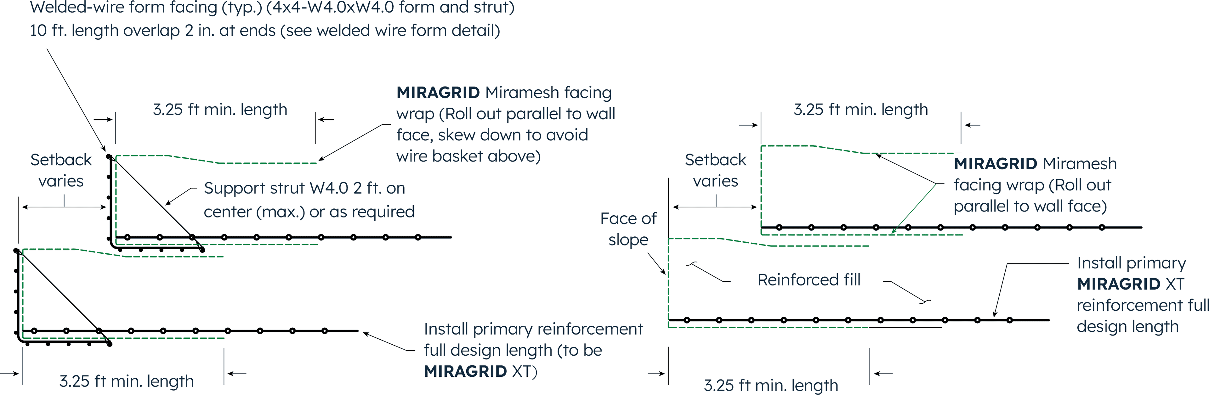
In wrapping the face of a slope, removable facing supports (e.g., wooden forms) or left-in-place welded wire mesh (WWM) forms are typically used. FHWA recommends the vertical reinforcement spacing for walls and slopes should be no greater than 32 inches (FHWA, 2009a). The vertical spacing of the primary reinforcement depends on the project conditions, facing type and construction methods. For instance, a vertical spacing of 18 inches (450 mm) is used where WWM forms are used, as shown in Figure 6(a) and 6(b). In practice, 18 inch (450 mm) vertical spacing is most common.

Figure 6(a): Typical Reinforced Soil Slope (RSS) with welded wire mesh (WWM) forms and MIRAGRID Miramesh GR face wrap
Figure 6(b): Project photo of WWM with MIRAGRID Miramesh GR during construction
Where WWM forms are not used, it is recommended to use temporary face support, like wooden forms, to allow for suitable compaction to the face of the RSS. These forms are then removed during construction. A typical geosynthetic wrapped face RSS that would be constructed using temporary wooden forms is shown in Figure 7(a) and (b).
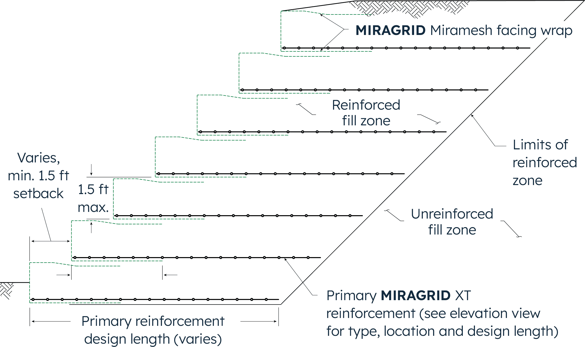
Figure 7(a): Typical RSS with MIRAGRID Miramesh GR geosynthetic face wrap

Figure 7(b): Project photo of MIRAGRID Miramesh GR face wrap installed with a temporary wooden form with a face batter angle [as opposed to the stepback typical detail shown in Figure 7(a)]
Whether using a WWM form or temporary face support, the geosynthetic face wrap should consist of materials that are UV stable and are designed for long-term use in environments with UV exposure. A structure is considered permanent if the design life is greater than 3 years (FHWA, 2009a). While vegetation can provide some cover and protection from UV, vegetated structures should consider the use of UV stable facing in the case vegetation is sparse. For vegetated structures, Solmax has several facing options to select the optimum face wrap for your project. One option is the use of MIRAGRID® Miramesh® GR which is a small opening mesh material to retain the soil at the face while allowing light penetration for vegetation growth.
MIRAGRID Miramesh GR has a design life of up to 75 years and is green in color to provide an immediate aesthetic look and blend into the vegetation while it is established. Typical RSS permanent structures with UV stable face wrap are shown in Figure 6 and Figure 7 and the face wrap details are shown in Figure 8.
Another option for wrapped face vegetated structures is the PROPEX Pyrawall® system. This system consists of a HPTRM geosynthetic wrap face of PROPEX Pyramat 75 combined with two internal fiber-composite braces installed within the geosynthetic material during manufacturing. These internal braces become the vertical and horizontal support when connected in the field with a third fiber-composite bracing strut.
This system is corrosion resistant because it contains no metal and is UV stable with a design life of up to 75 years. A typical PROPEX Pyrawall RSS cross section is shown in Figure 9(a) and a completed PROPEX Pyrawall project photo is shown in Figure 9(b). The PROPEX Pyrawall system can also be used without primary MIRAGRID XT geogrid einforcement in short slopes, the height cutoff is dependent on the soil strength parameters and the loading conditions for each project.
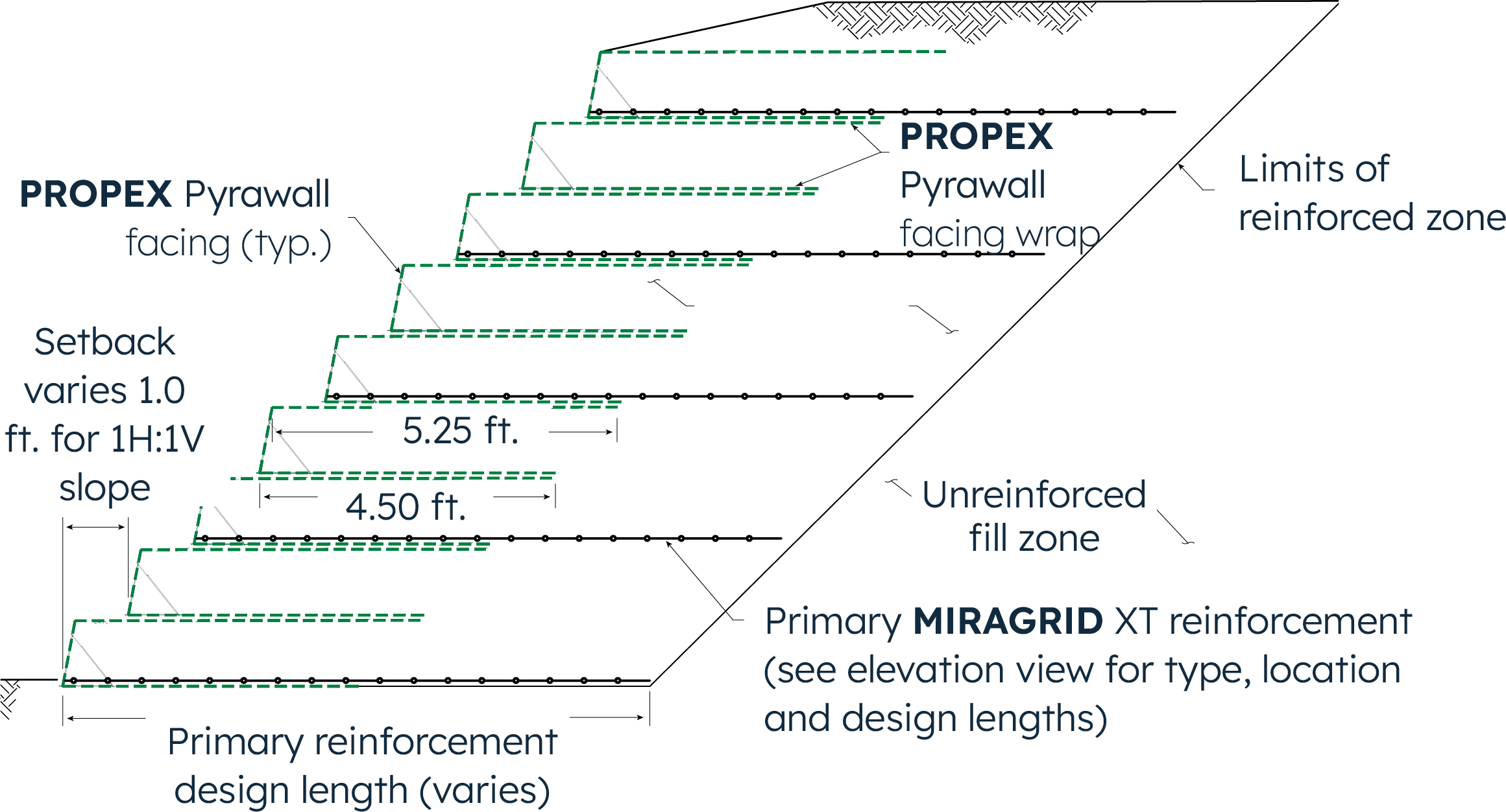
Figure 9(a): Typical cross section of a slope with PROPEX Pyrawall facing
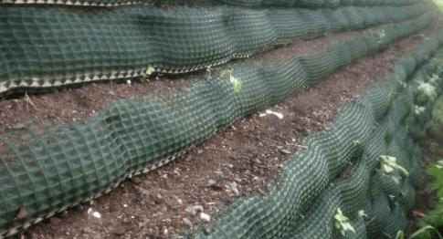
Figure 9(b): A completed PROPEX Pyrawall installation
Pictures of the WWM with MIRAGRID Miramesh GR wrap face and the PROPEX Pyrawall prepared for geogrid reinforcement and compacted fill placement are shown in Figure 10(a) and 10(b), respectively.
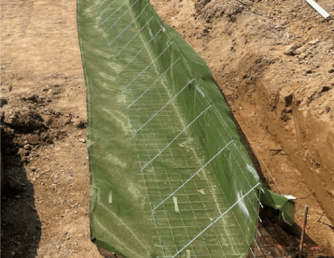
Figure 10(a): WWM with MIRAGRID Miramesh GR face wrap
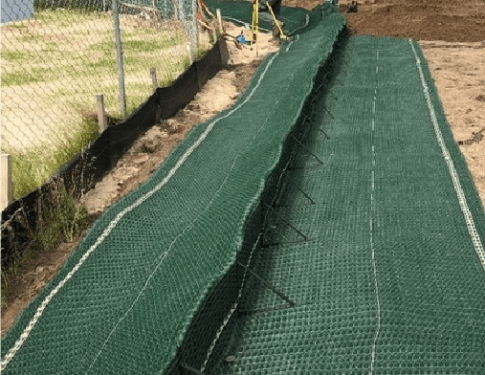
Figure 10(b): PROPEX Pyrawall face wrap system
Temporary RSS structures have a design life of less than 3 years and therefore wrapped face geosynthetic structures are not required to resist UV degradation. In these cases, the geogrid reinforcement (which is typically not UV stable) can wrap up the face. When wrapping the slope face, the reinforcement is turned up at the face and returned a minimum of 3 feet (1 meter) into the slope below the next reinforcement layer (FHWA, 2009b). In structures where the geogrid is wrapped up the face, a geotextile fabric may be required at the face to retain backfill soils, particularly for slope lifts steeper than 1(H): 1(V). The geogrid with geotextile wrapped face detail is shown in Figure 11(a) and a MSE wall under construction showing the use of the temporary wooden form and the geogrid and geotextile wrap face in Figure 11(b).
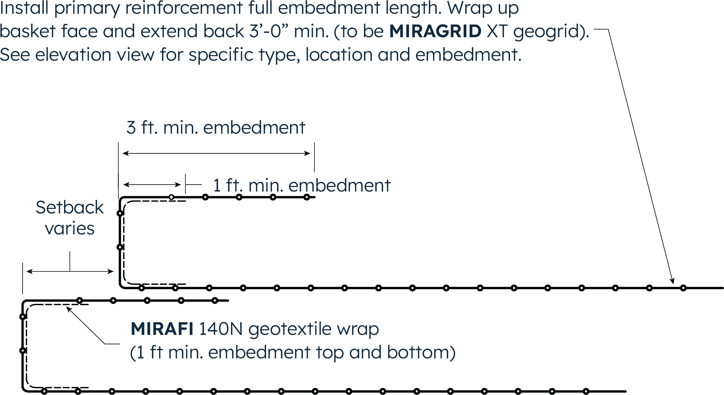
Figure 11(a): Temporary RSS with geogrid and geotextile wrapped face
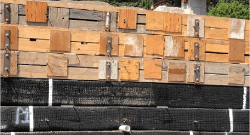
Figure 11(b): Project photo of MIRAGRID XT geogrid wrapped face MSE wall under construction
Slope facing system requirements depend on soil type, slope angle, and reinforcement spacing. Slopes steeper than 1(H): 1(V) should be constructed with facing support. Facing options for various slope angles are shown in the Table entitled RSS Facing Options on the last page of this Technical Note (modified from FHWA, 2009b).
Secondary reinforcement may be required at the face of reinforced slopes. Secondary layers of reinforcement aid in achieving compaction at the face, thus increasing soil shear strength and resistance to erosion (FHWA, 2009b). These layers also act as reinforcement against shallow or sloughing types of slope failures. The need for secondary reinforcement is dependent upon soil type, slope angle, slope height, and primary reinforcement spacing.
Secondary reinforcement should be placed in continuous layers and does not need to be as strong as the primary reinforcement, but it must be strong enough to survive construction and provide localized tensile reinforcement to the surficial soils (FHWA, 2009b). Secondary reinforcement is typically placed on each or every other soil lift, except at lifts where the primary reinforcement is placed. Secondary reinforcement is also placed at the same elevation as the primary reinforcement when primary reinforcement is placed at less than 100% coverage in plan view. Typically, secondary reinforcement extends 4 to 6.5 feet back in the fill, from the face of the slope (FHWA, 2009b). However, longer lengths may be required if large seepage forces at the face are likely to develop. A detailed analysis may be performed using the method described by Thielen and Collin (1993) for critical applications or where large seepage forces may develop.
In cases where surficial slope stability (shallow or sloughing failures) or erosion is the concern, another option, especially useful in cut slopes, is the PROPEX Armormax® system. This is the combination of PROPEX Pyramat 75 with earth anchors to stabilize up to the upper 3 feet of the slope face. There are two different earth anchor sizes utilized for surficial stability, the B2 and B3 anchors, with a length of 6 ft and 9 ft, respectively. These anchors allow for installation into the slope face, which in conjunction with the HPTRM PROPEX Pyramat 75 along the face, stabilize the top shallow soil surficial failures that can develop, especially in slopes where primary and secondary geogrid reinforcement is not utilized. The PROPEX Armormax system is suitable for surficial stability and is only applicable for slopes equal to or less steep than a 1(H) : 1(V) slope angle. A typical PROPEX Armormax cross section is shown in Figure 12(a) and a project photo of the system during anchor installation is shown in Figure 12(b).

Figure 12(a): Typical cross section for surficial stability with PROPEX Armormax 75
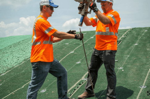
Figure 12(b): Project photo of PROPEX Armormax 75 earth anchors being installed
FHWA. (2009a). Federal Highway Administration FHWA-NHI-10-024 “Design of Mechanically Stabilized Earth Walls and Reinforced Soil Slopes” - Volume I. Washington, D.C.: NHI.
FHWA. (2009b). Federal Highway Administration FHWA-NHI-10-025 “Design and Construction of Mechanically Stabilized Earth Walls and Reinforced Slopes” - Volume II. Washington, D.C.: NHI.
Thielen, D.L., and Collin, J.G. (1993) “Geogrid Reinforcement for Surficial Stability of Slopes”, Geosynthetics ‘93 Conference Proceedings, pp. 229-241, Vancouver, Canada.

(1) Slope height cutoffs for requirement of MIRAGRID are estimates and will vary based on soil strength parameters and loading conditions.
(2) All WWM w/MIRAGRID Miramesh requires MIRAGRID in conjunction with facing.
(3) NR = Not recommended
(4) Hard Facing is not required for <45°, however WWM is still used in some cases.
(5) Evaluate the need for MIRAGRID reinforcement for RSS stability in conjunction with PROPEX Armormax/PROPEX Pyramat
(6) Hydraulic loading requires additional analysis, erosion protection at the face can be achieved with wrapped face geosynthetic with resistance to shear stress. Other options such as PROPEX Scourlok should be considered.
(7) All of these options require MIRAGRID reinforcement. The only exception is where analysis shows that PROPEX Pyrawall is satisfactory without primary reinforcement.
(8) All options require design by a licensed engineer to include internal, external, and global/compound analysis.
Figure 1: Typical Reinforced Soil Slope (RSS) cross section
Figure 5: Typical reinforced soil slope with geotextile filter fabric placed under the rip rap face protection
Figure 8: Face wrap details for permanent RSS structures with MIRAGRID Miramesh GR